- Quick Jump:
- Bodyshell removal
- Truck Disassembly
- Mechanism Disassembly
N Scale North American Locomotives |
HomeProduct Maintenance |
GG1 |
| Picture (Click to Zoom) | Directions |
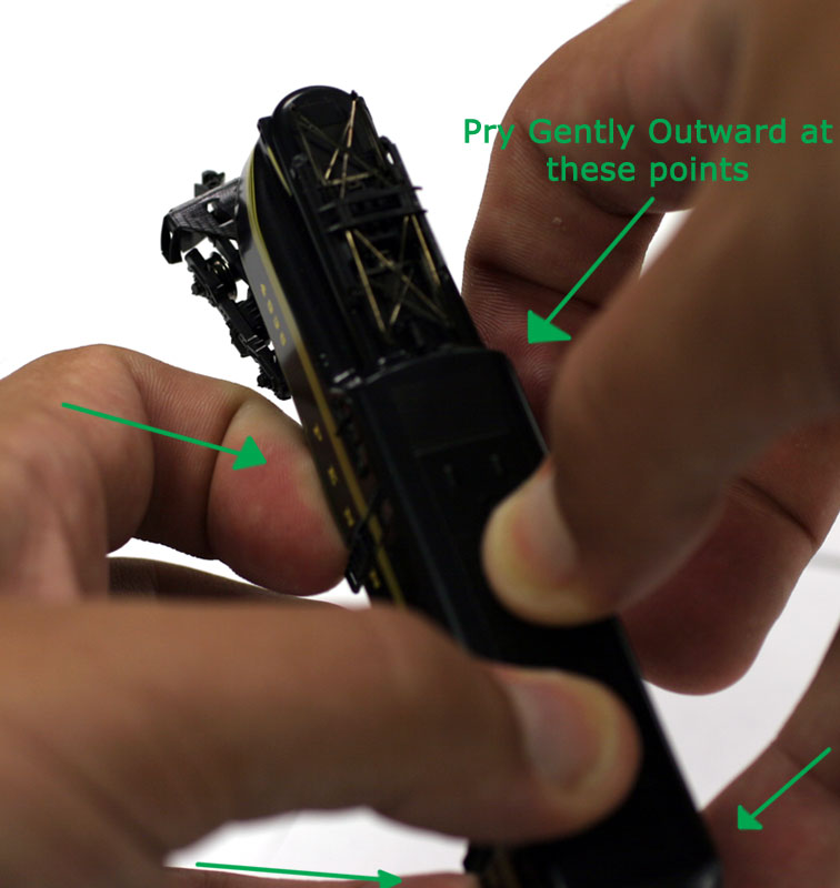 |
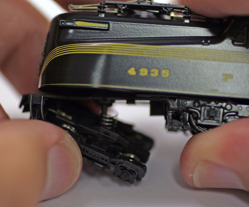
Step 1: Bodyshell Removal The shell of the GG1 is held in place by four friction-fit clips just below the cab windows. To free the shell, simply grip the GG1 as shown with your thumbs on top of the locomotive, and pull outward on the shell with your fingers in the four places as shown. Be sure you are spreading the shell on the outside of the ladders, not the inside. When the shell comes free you should feel the weight inside shift. At this point you no longer need to spread the shell sides, and you can simply tap the mechanism out of the shell and into your hand. |
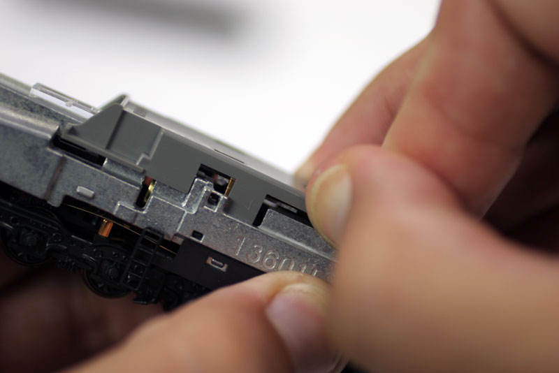 |
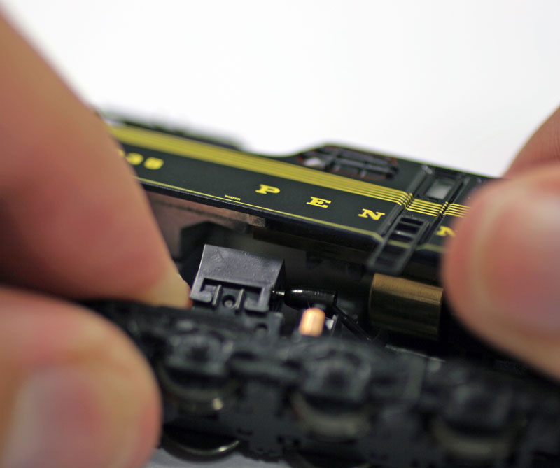
Step 2: Accessing the lightboard For most DCC installation, you will need to replace the light and circuit board which is held in place beneath the grey plastic cover at the top of the mechanism. Take care to note the two clear plastic light tubes, which transmit the light from the board to the head and tail lights. Please note that some decoders will NOT use these pieces; check with the dimensions of your particular decoder for specifics. The Grey cover is held in place by two long arms which slide down into the mechanism, shown in the photo. By prying just beside these arms, you can begin to slide them free from the body; be sure to alternate between sides as you free them, so they come up evenly and do not get bent or damaged. |
|
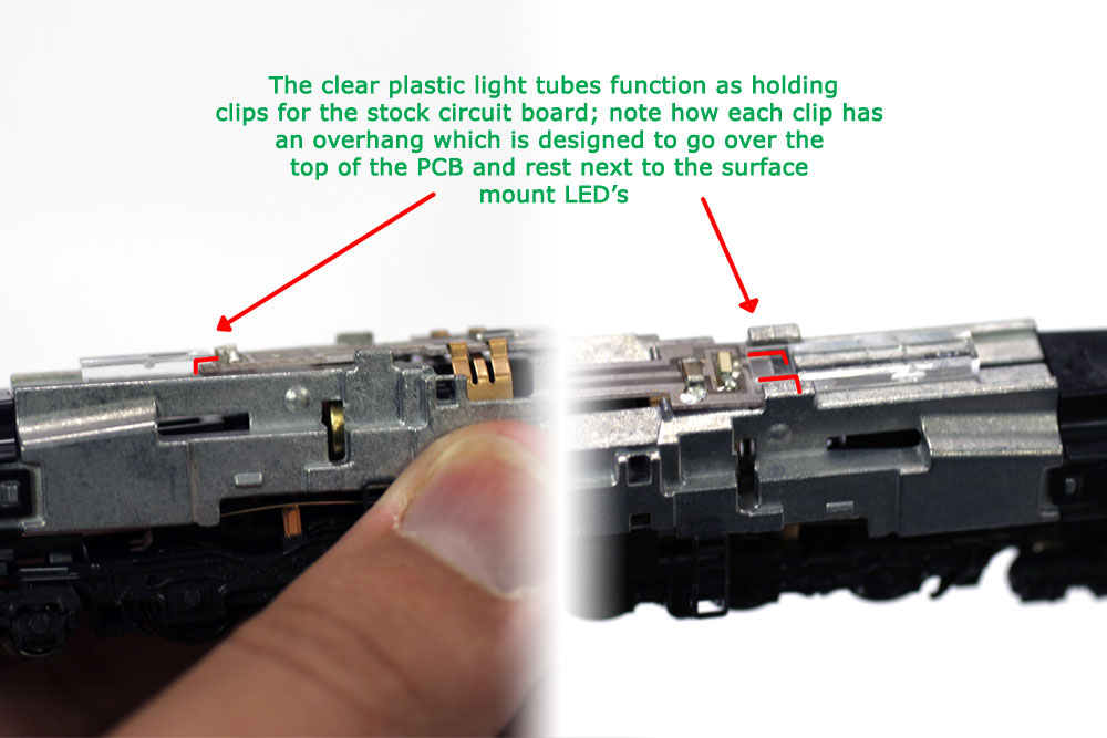
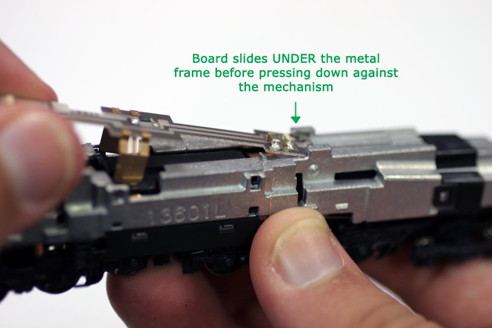
Step 3: Removing/Replacing the Lightboard and light tubes When both taking out and putting back in the stock PCB board, take care to note how it interacts both with the locomotive frame and the clear plastic light tube extensions. As shown in the two images to the left, the board is held down both my a metal overhang as well as extensions of the light tubes; when taking the board out and putting it back in, be careful to get all of these pieces aligned properly to ensure correct electrical contact as well as that the body shell will sit properly and all lights function as designed. |
 |
Overview: Stage 1 Disassembly For the majority of DCC installations, it's at this point that you don't need to disassemble the GG1 any further. Take note of the which side the clear plastic tubes go on, as well as which direction is "forward" for the lightboard with relation to the bodyshell. The mechanism halves each have an "L" and "R" molded into the side to make it easier to determine which way is "forward". Continue reading below for directions on how to remove and disassemble the truck components. |
| Picture (Click to Zoom) | Directions |
 |
Step 1: Removing the Pilot Trucks Each pilot truck on the GG1 is held in place by a snap-in post that is surrounded by a cushioning spring. The truck can be popped free of the whole assembly by supporting the power truck from below with your thumb and the snowplow on the front while pulling the pilot truck down and away from the support beam. Take care with the coupler, as it is threaded through the front pilot and will come away with the pilot truck when removing. Be sure to bend the truck down and away from the power truck to allow the coupler to slip through the gap there. This is much easier if the trip pin is not installed. |
 |
Step 2: Removing the Driving Truck and Pilot support Like the pilot trucks, the Drive Truck assembly is held into the mechanism with a snaplock. By firmly gripping the body of the locomotive and the power truck, and pulling straight down, the entire assembly will come away as a complete unit. Take care not to lose the universal that connects each truck to the locomotive's motor; this can come lose when removing the truck and is the only lose part between the truck and the chassis. |
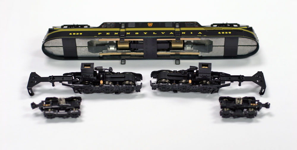 |
Overview: Stage 2 Disassembly Removing the trucks will allow you to change or re-set the couplers on the locomotive, as well as provide access for lubricating the drive gears (by removing the gearcase cap on top of the truck) for lubrication. Take care not to lose either the cushioning springs for the pilot truck or the universal that connects the worm gear to the locomotive motor when doing this. Further disassembly can be accomplished, but is not recommended, by freeing the holding tabs on the various sideframe assemblies on the trucks. Continue reading below for directions on how to remove and disassemble the mechanism. |
| Picture (Click to Zoom) | Directions |
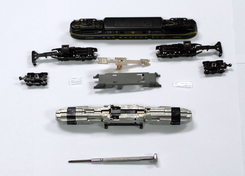 |
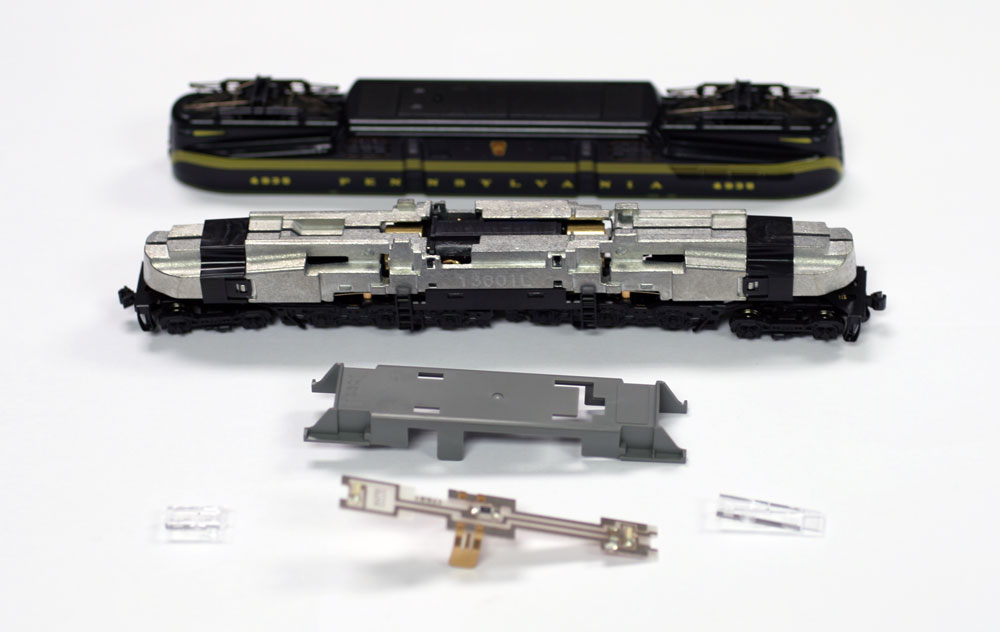
Before Beginning Having followed the above stages of disassembly, you should have the GG1 broken down as shown to the left. The following directions will show you how to completely disassemble the remaining chassis, should you need to replace or lubricate the motor. You will need a small, flat head jeweler's screwdriver for this stage in order to loosen various clips that hold the chassis together. |
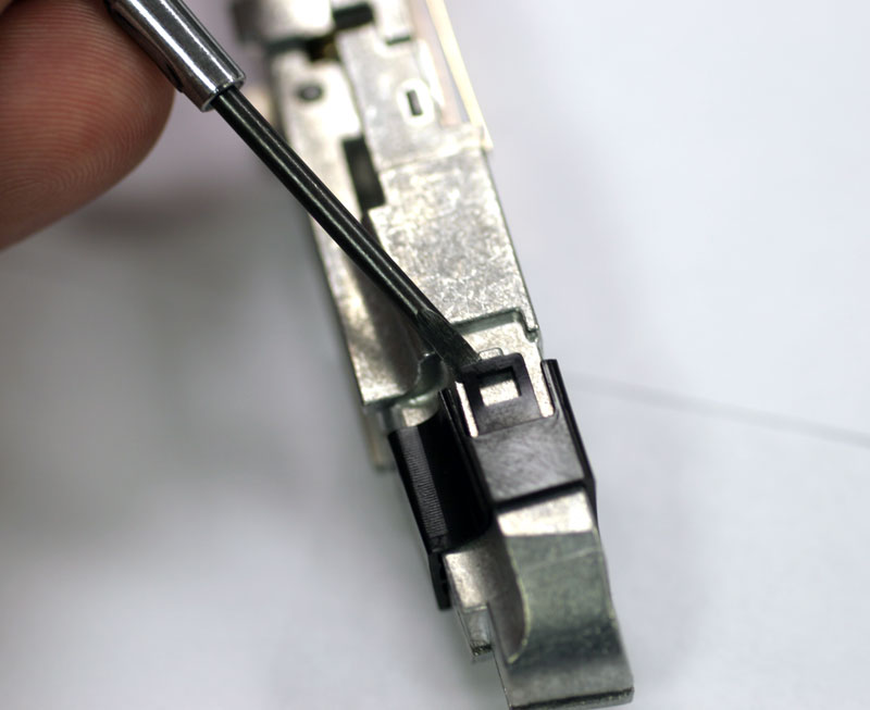 |
Step 1: Removing the frame binders The mechanism of the GG1 is held together by two black plastic binders, each of which is held to the metal frame by two clips, one on each side. In order to separate the frame halves, you will need to use your screwdriver to gently pry the black plastic tab on each side up and away from the body, while prying the binding piece away from the center. Once both sides are freed, you should be able to slide the binder off of the chassis without incident. Fingernails help for this step, but are not necessarily required. |
 |
Step 2: Removing the Ladder assembly With the two outer binders removed, the black base piece with the four attached ladders should essentially fall off of the locomotive. |
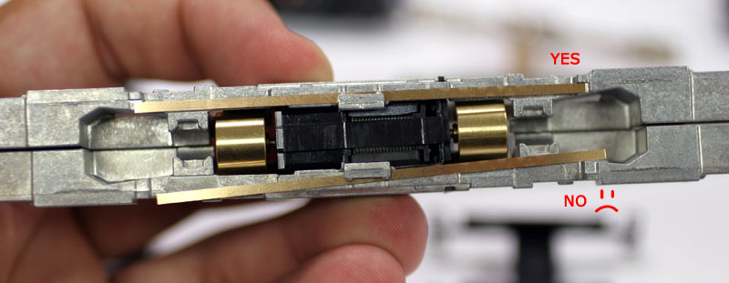 |
Step 3: Electrical pickup strips The two electrical pickups can be left attached to the chassis, but are just as likely to fall off during the process of disassembly. Shown to the left are both the correct, and incorrect, ways that the strips can end up when seated in the chassis. If the strips are not correctly aligned, the pickup wipes from the trucks can also become misaligned, causing derailments or poor electrical connectivity. Always ensure that the electrical pickups are correctly seated and that the truck pickup wipes are pushing up into the underside of them instead of lying flat against their inside edge. |
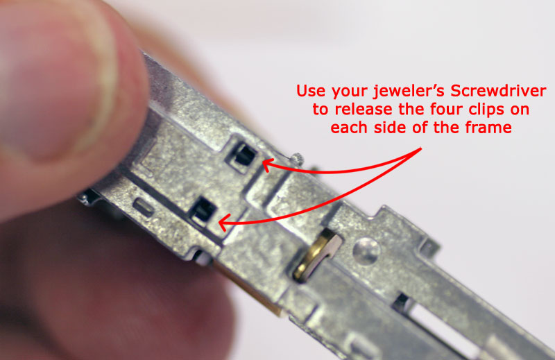 |
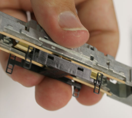
Step 4: Releasing the Motor Saddle The final stage of disassembly will be freeing the motor itself. The motor sadle is suspended between the frame halves by eight soft plastic arms which grip the frame at four points on each side. Release these grips with your jeweler's screwdriver to separate the frame halves and gain access to the motor. |
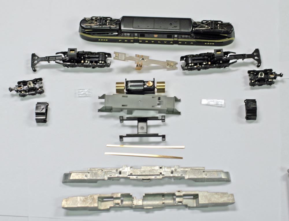 |
Overview: Final Stage Disassembly The resultant debris field shown to the left is what your GG1 should look like once it has been disassembled down to its component assemblies. Further disassembly of the trucks is possible but not recommended due to complications with realigning drive gears and should not be attempted by those who are not already familiar with the mechanical workings of modern kato trucks. If you need for some reason to break down the trucks further and you are not comfortable with the process, we recommend you take your GG1 to a local hobby store if they have a repair department, or that you send the truck or locomotive to us for service. To reassemble the GG1, simply follow the above steps in reverse. |