N Scale North American Locomotives |
HomeProduct Maintenance |
GS-4 |
| Picture (Click to Zoom) | Directions |
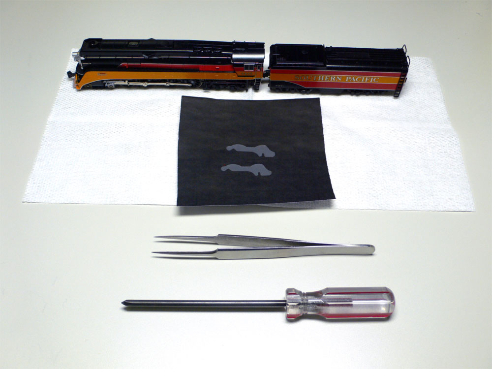 |
Step 1: Tools and Preparation You will need a pair of needlenose tweezers and a GS-4 DCC Retrofit kit to perform this installation. Should you need to remove the lower frame in order to remove the spacers or adjust their positioning, you will also need a small phillips screwdriver. BEFORE YOU PERFORM THIS OPERATION: Make sure that your GS-4 DOES NOT ALREADY HAVE THESE SPACERS INSTALLED. If the locomotive is from a later production run or has already been back to Kato USA for any repairs, it should already have the spacers installed. Look between the wheels for the spacer to make sure that this installation is necessary. |
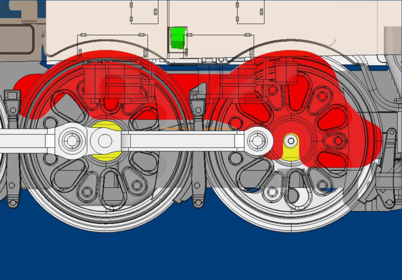 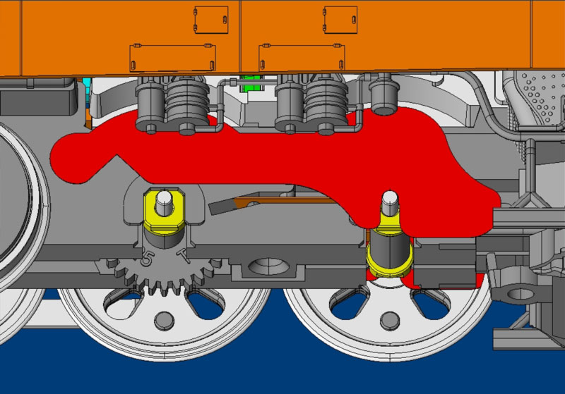 |
Step 2: Explanation The DCC insulating spacers go into the wheel wells of the GS-4 behind the 3rd and 4th driver. One insert will go on either side of the locomotive; a total of two inserts. Each kit includes four inserts in the event that any are damaged during the installation. Click the images to the left for engineering diagrams of where the spacers will be located once installed. |
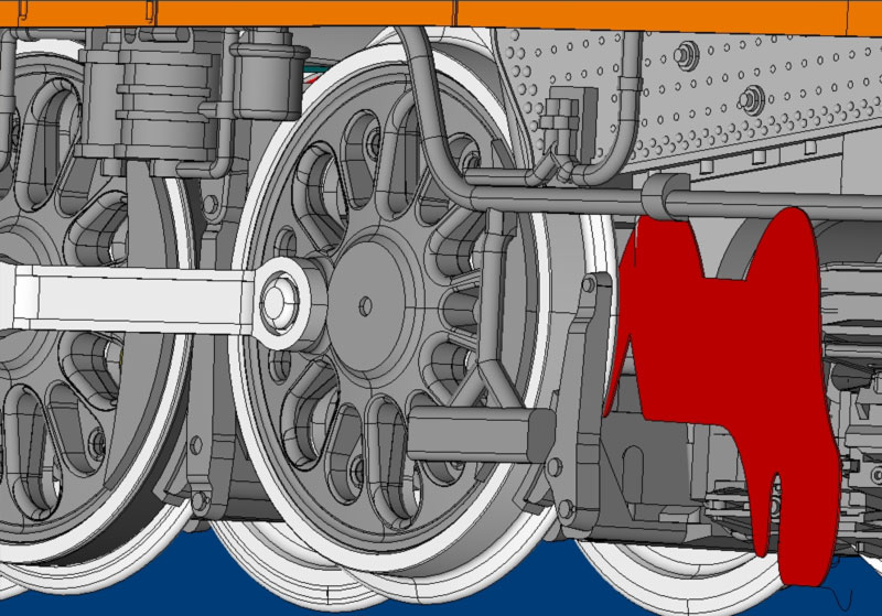 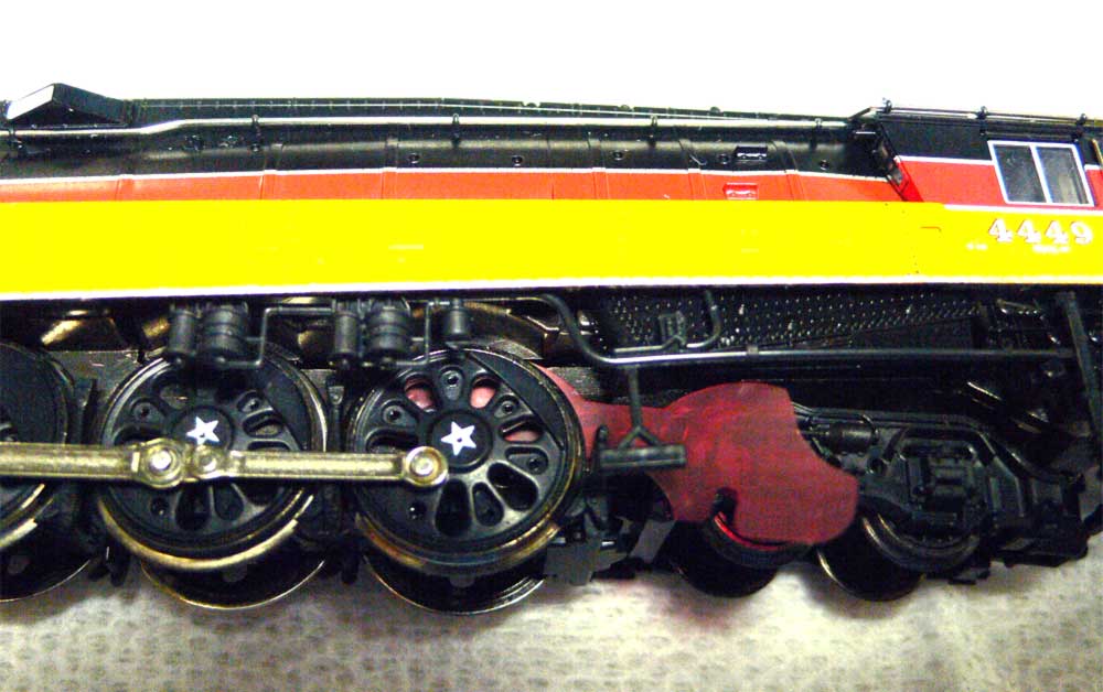 |
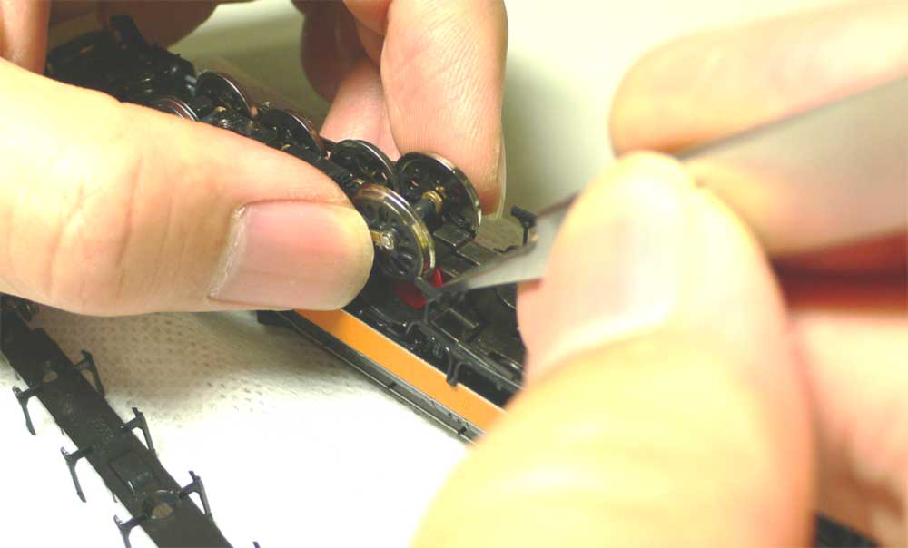
Step 3: Inserting the spacer The spacer slides in from the rear of the locomotive as shown. Push inward on the drivers from the opposite side to push the wheels out from the body and give yourself room to work. Please note that the spacer in these images has been colored red to make it more visible. |
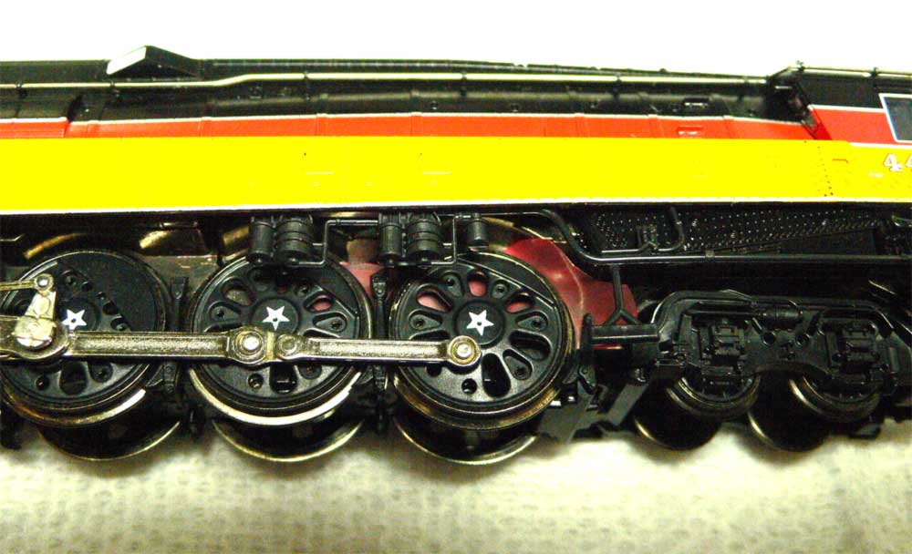 |
Step 4: Inserting the spacer (continued) The spacer may need to be allowed to bend a little to get it around the lip of the wheel wells. Be sure that the spacer does not CREASE during the installation process, however. If you notice that the spacer has creased or developed a significant bend to it, discard it and start over. |
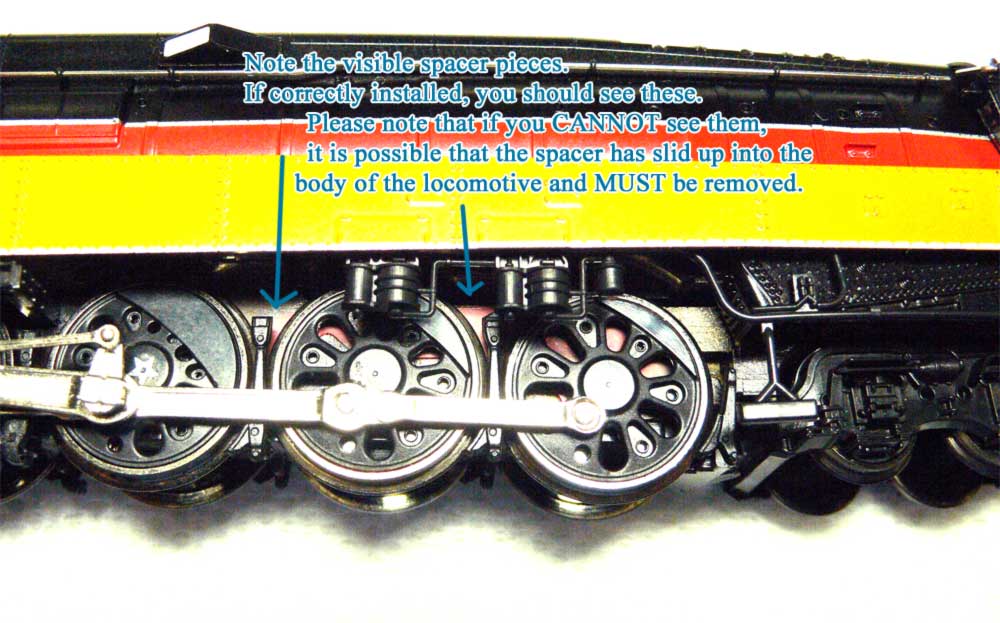 |
Step 5: Checking your work When correctly installed, you should be able to see the spacer through the wheels and undercarriage as shown in the image to the left and in the drawings in step 2. If you look and you CANNOT see the spacer through the cracks, you will have to remove the underbody of the GS-4 and remove the spacer and start over. If you can see the spacer, repeat the installation process on the opposite side of the locomotive. When this is done, the GS-4 will be ready to run on DCC. |
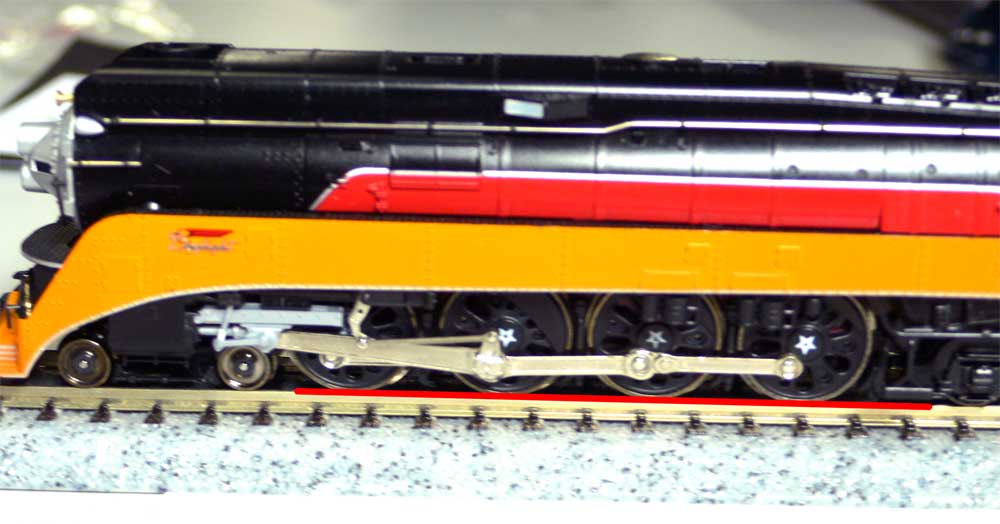 |
Step 6: Final check With the two spacers installed, place the locomotive on the track and ensure that A) all drivers are straight and touching the track, and B) that the fourth driver is springing cleanly on its shocks. Finally, be sure to test-run the GS-4 and listen to it running; if it makes any "clacking" noises (akin to the sound of a baseball card in the spokes of a bicycle), one of the spacers is probably creased or bent and is coming into contact with the wheels and should be replaced. For instructions on how to remove the spacers, see below. If everything checks out, and the locomotive moves freely, the GS-4 DCC Retrofit kit installation has been successfully completed and the GS-4 is ready for tender-installed DCC Decoders. |
| Picture (Click to Zoom) | Directions |
|
Step 1: Tools and Preparation You will need a pair of needlenose tweezers and a small phillips screwdriver. You will only need to do this IF for some reason a spacer was damaged during installation, or was incorrectly installed. |
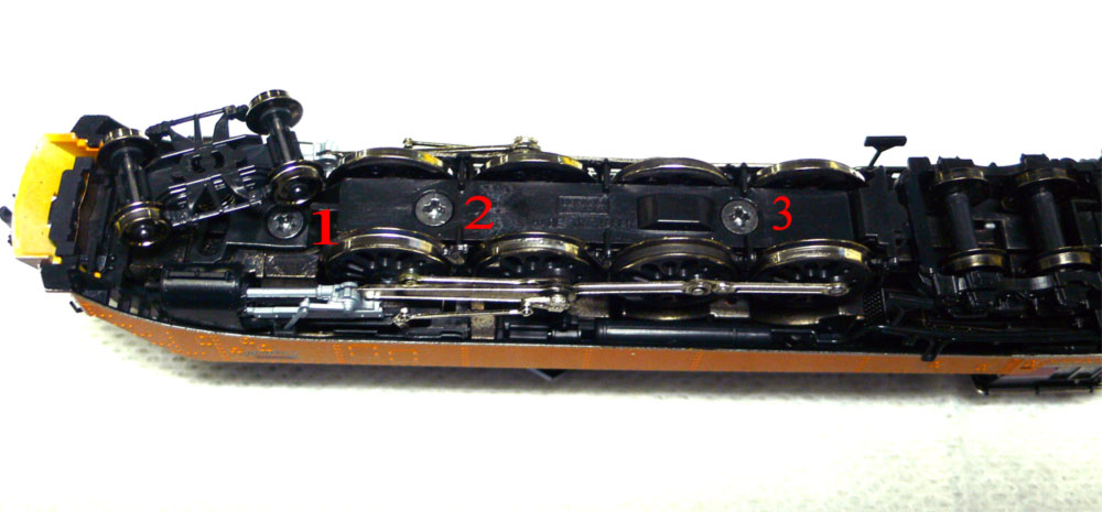 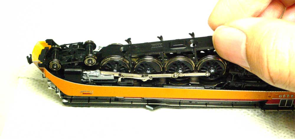 |
Step 2: Unscrewing the underframe There are three screws securing the plastic underframe to the body of the GS-4, as shown. Be careful when you are removing these to keep the GS-4 upside down, as once the frame is removed, there will be nothing holding the drivers in place. Please take note that there is a tab locking the front of the plastic frame into the underbody, just in front of the lead truck. Lift from the rear as shown to correctly remove this piece. |
 |
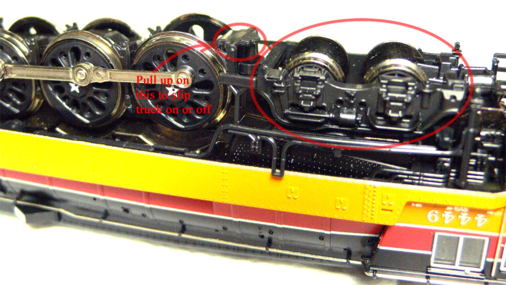
Step 3: Removing the spacers Carefully, and most importantly WITHOUT disturbing the third (geared) driver, lifting up the fourth (rear) driver will give you access to the spacers and allow you to remove them. Again, the spacer in these images have been colored red to make them more visible. |
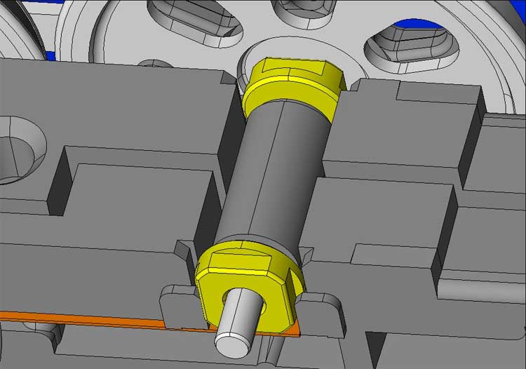 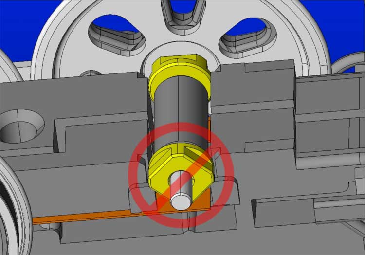 |
Step 4: Putting the driver back correctly The brass bushings on the GS-4's drivers have squared edges that must be correctly aligned in order for them to sit in place correctly. Notice in the images to the left the correct way, and incorrect way to seat the bushings. If they are incorrectly seated, the fourth driver will not lock in all the way, and will lose its sprung properties, causing the locomotive to run poorly, if at all. Also take care to make sure that the siderods are lined up correctly |
 |
Step 5: Replacing the underframe Once the drivers are back in place and correctly situated, you can put the underframe back on. Remember again that the front of the piece has a locking tab under the leading truck, so insert the front first (an exact reverse of the way you removed it). |
 |
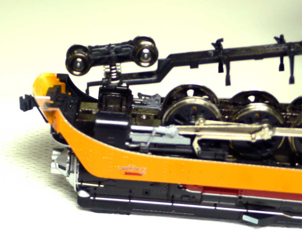
Step 6: The Rear truck If the rear truck has come off or you forgot to put it back in place when replacing the underframe, it can be put back place by carefully pulling upward (if the unit is upside down) on the rear of the underframe and sliding the truck in place. Make sure that the truck is correctly oriented with the exposed wheels facing towards the track as shown. |