GE P42 "Genesis" |
| Picture (Click to Zoom) | Directions |
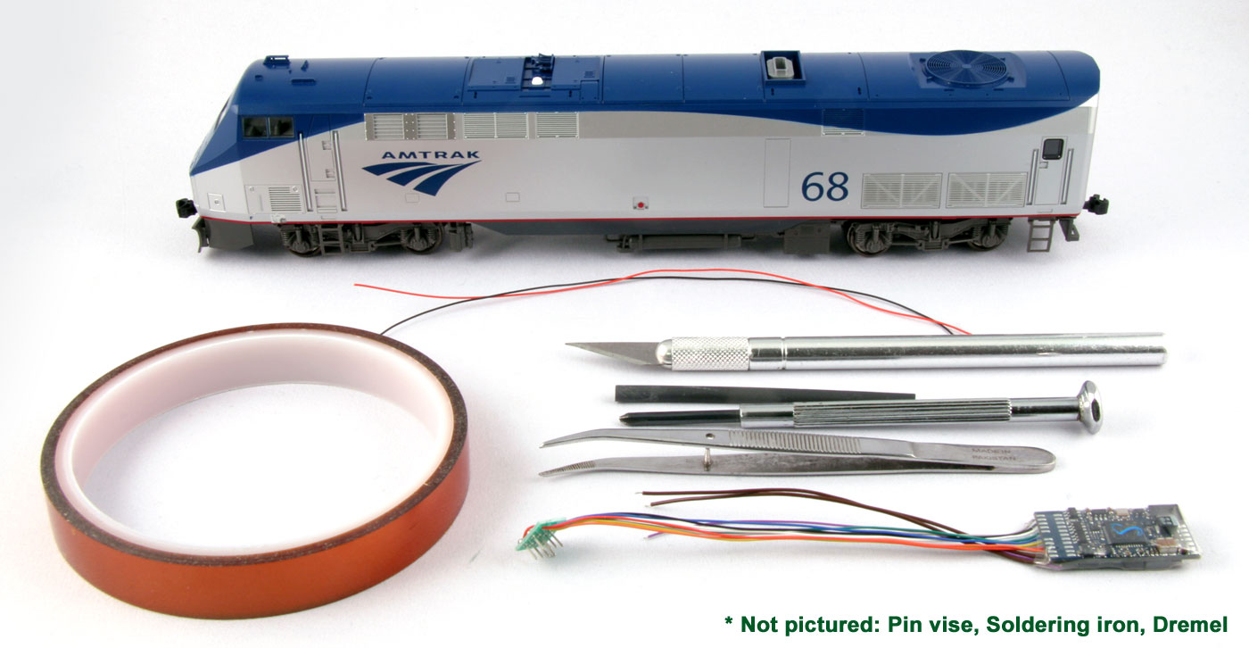 |
Step 1: Tools and Preparation Installation of DCC into the HO GE P42 will require the following tools and parts:
|
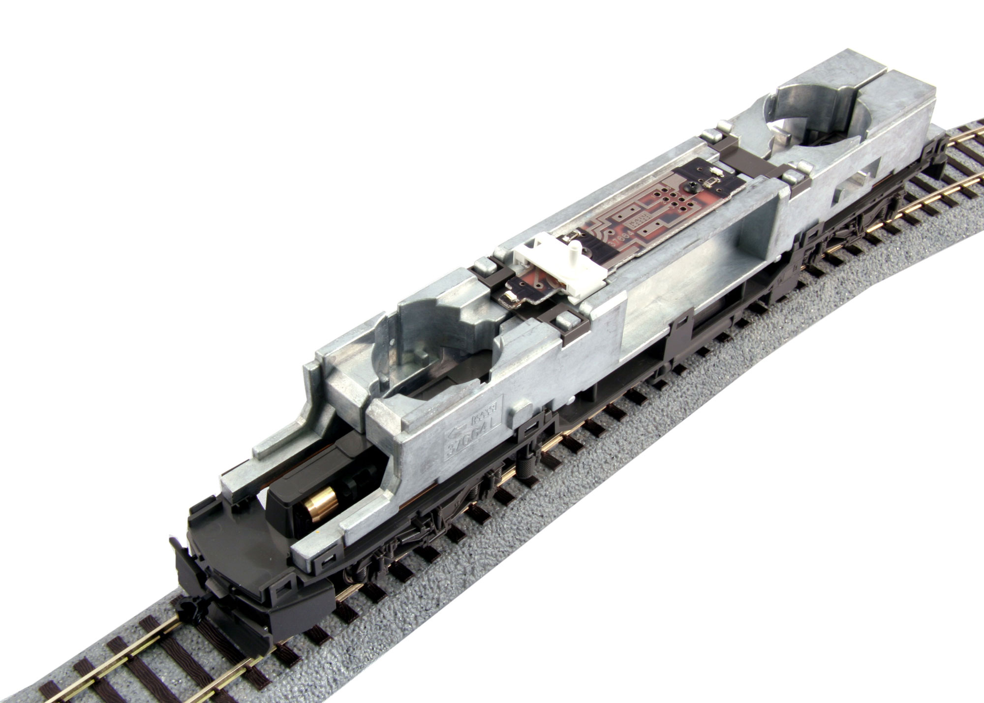 |
Step 2: Remove the Bodyshell Remove the bodyshell by gently prying the shell away from the body, pulling out at the points directly above the trucks. This will release the shell from the mechanism and allow you to pull it off, leaving you with the exposed mechanism (shown). The couplers do not need to be removed to remove the shell. Note: You will want to remove and set aside the ladders at this point so that you do not lose them. |
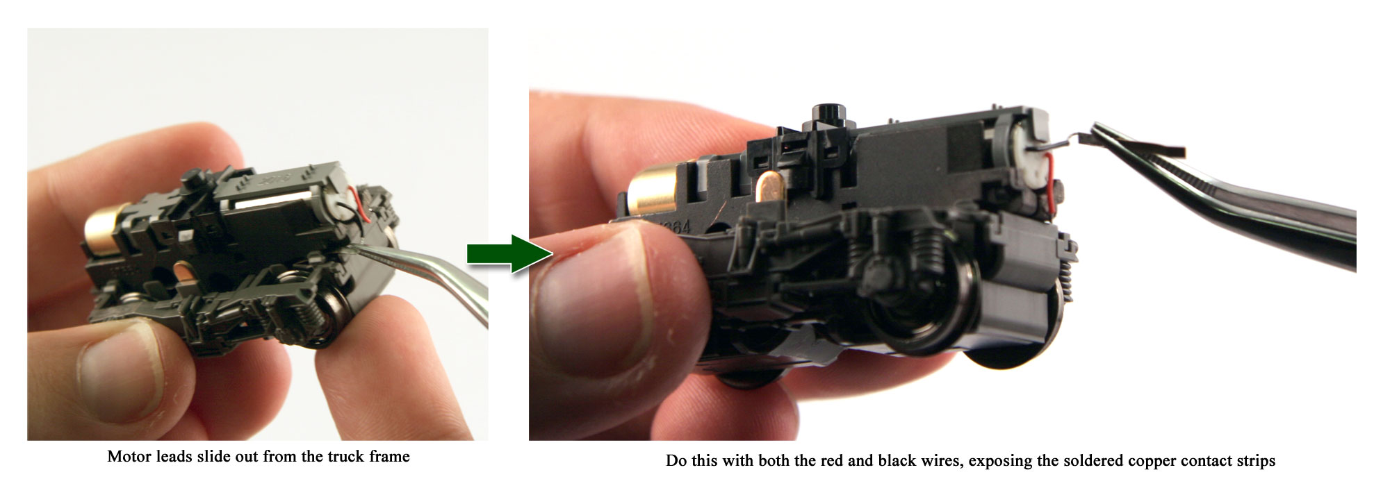 |
Step 3: Removing and preparing the trucks The locomotive's trucks are snap fit and can be removed by twisting and pulling them off of the body. Once removed, you will need to expose the motor leads in order to route them through the locomotive's circuit board (where we will be installing DCC) instead of them picking up electricity directly from the track and wheels. |
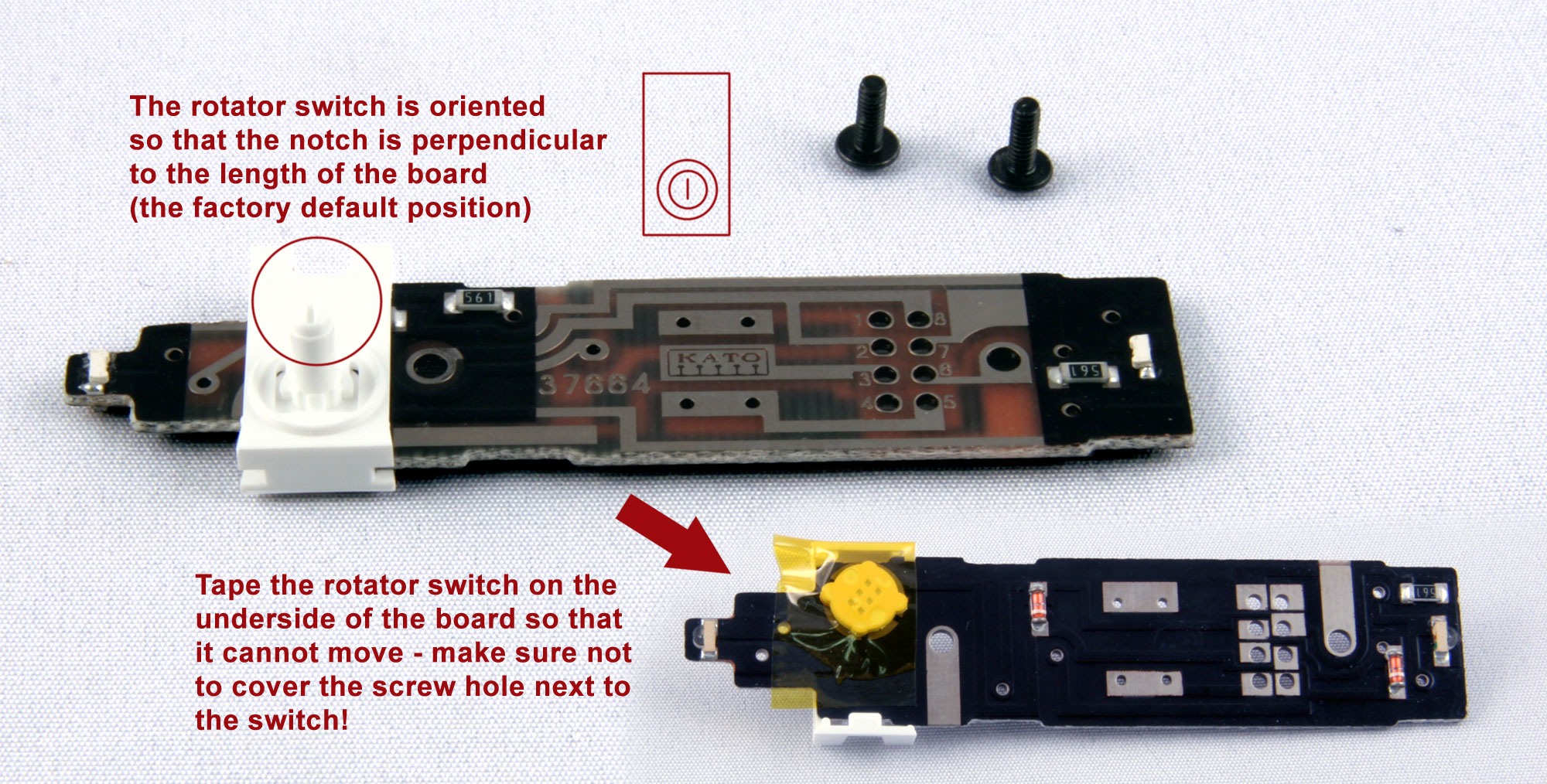 |
Step 4: Remove and prepare the circuit board for modification Using your phillips screwdriver, remove the two screws holding down the factory circuit board. This will free the circuit board and GPS dome rotator switch assembly. Make sure that the GPS dome switch is rotated so that it is in the default position (as shown in this image), and then use a piece of Kapton or electrical tape to secure the rotator from the underside (to prevent it from being moved) - this is so that we can ensure that all light control will be handled by the DCC board rather than through the analog selector switch. |
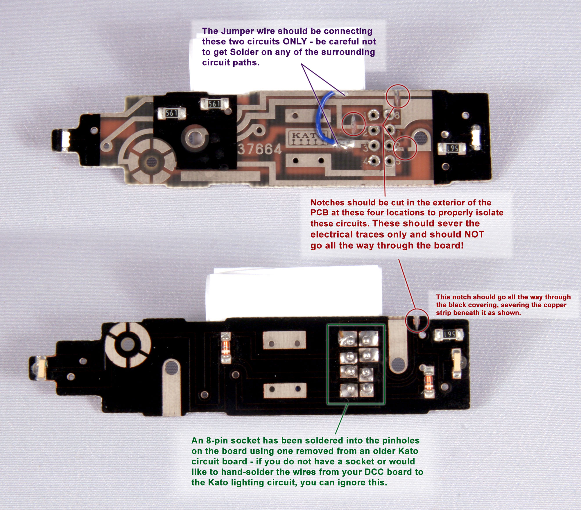 |
Step 5: Cutting traces and soldering a bypass wire + 8-pin socket In order to modify the board to take a DCC decoder, you will first need to cut four (4) traces on the board (as shown in the image) - three (3) on top of the board and one (1) on the underside. Carefully sever the electrical circuits in the locations shown in the photo using your hobby knife or rotary cutting tool, being extremely careful not to cut all the way through the board or cut any of the other electrical circuits. Once the traces have been cut as shown, you will need to solder a small piece of wire, approximately 3/4 of an inch long into place as shown on the image, connecting the upper circuit as shown to pinhole number three. Consult the image to the left for the exact placement. Make sure that your wire and solder are only connecting the upper circuit and the center circuit. Finally, if you wish to have an 8-pin plug-and-play option for your decoder and do not intend to solder the wires or pins directly to the board, you can solder eight (8) pin sockets into the blind holes on the factory circuit board as shown in the image - for this project, these sockets were removed from a spare Kato #958033 RS-2 circuit board, but the sockets are also made available by various DCC manufacturers. |
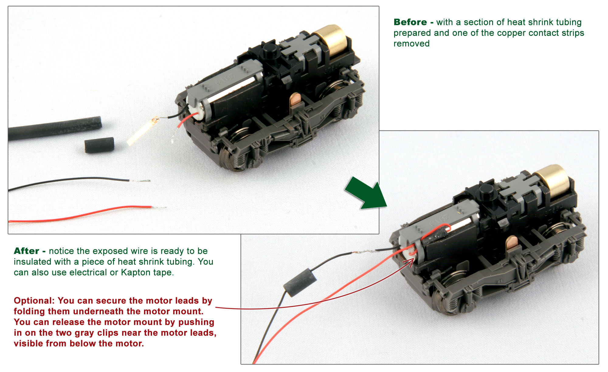 |
Step 6: Attach wire leads to the trucks Using a soldering iron and a pair of tweezers, heat up the brass strips and remove them from the motor leads on the truck. Cut four pieces of wire, approximately 6 inches in length (longer is better - you can always cut it shorter later!) to make it easier to keep track, we recommend matching the red and black wire pattern of the motor leads. Carefully tin and splice the stripped ends of these wires to the motor leads. Utilizing some heat shrink tubing (or some small pieces of electrical or insulated tape) insulate these splices. |
|
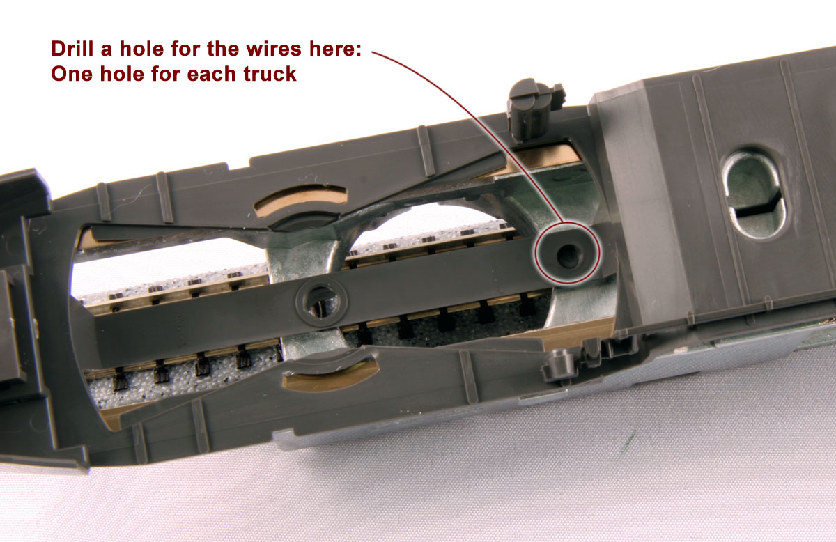
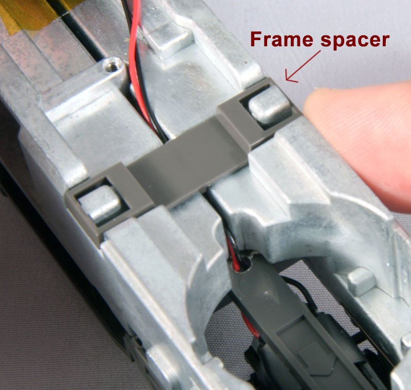
Step 7: Modify the bolster assembly and reinstall the trucks Turning over the model, you will see 2 divots on the underside (approximately 1/8" in diameter of the plastic mounting bracket between the mounting peg and the fuel tank (see photo #1) - using your pin vice, drill the remainder of the way through this divots, one per truck, being careful not to put too much pressure on the plastic or make too large of a hole (and possibly breaking the plastic mount as a result - for this reason a hand drill such as a pin vice is recommended rather than using a Dremel). Thread the longer wires that you soldered to the trucks through these holes and reattach the trucks to the chassis - when reattaching the trucks, the front truck is marked with an "F" on the underside and the rear with an "R", while the arrow molded on the underside should always point towards the nearest coupler and away from the fuel tank. To ensure the wires are seated correctly and will not interfere with the movement of the trucks, remove the gray frame half spacers from the top of the mechanism (photo #2) and feed the wires from the trucks between the frame halves and underneath where the gray clips are mounted, being sure to test the wiggle of the trucks to ensure that the wires or not being pulled so tightly as to restrict their movement. |
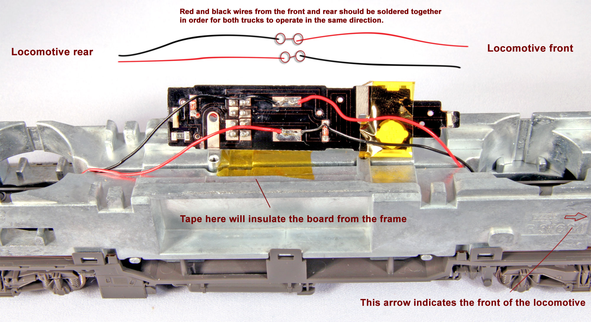 |
Step 8: Solder the truck wires to the modified circuit board Take the right front lead (red if you matched it to the color of the motor) and splice/solder it to the rear right lead (which should be black if you matched the motor). Repeat this process with the front left (black) and rear left (red) wires. This will wire both motors together so that they will both react in tandem to controls from the decoder. On the underside of the modified circuit board are two metal pads (each with two small holes); these are where you will want to attach the motor leads. Taking care that you have the circuit board oriented in the correct direction (the white rotary switch should be on the side closest to the front of the locomotive) solder the pair of left side leads to the left underside of the board, and do the same for the right. When you are finished, it should look as shown in the image to the left. At this time you will want to place a square of Kapton tape on the frame below where the lightboard will rest (as shown) - this will insulate the frame from the modified circuit board and protect the DCC plug. |
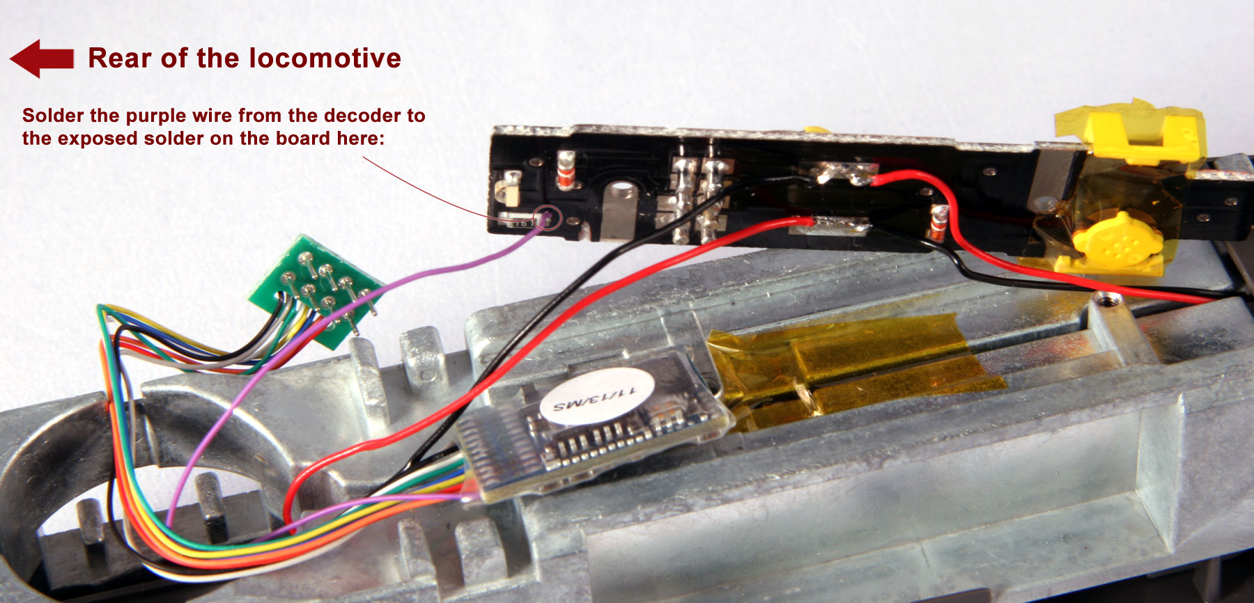 |
Step 9: Solder the rear marker light control and re-seat the board Even if you are using an 8-pin plug, you will need to solder the purple wire from your DCC decoder harness to the lower, rear LED in order to control the rear tail lights (F2 on most DCC decoders). See the picture to the left for where to solder the wire. Once you have finished soldering wires, re-seat the board on the mechanism and use the screws you removed in Step 4 to secure it. Take care when you're seating the board that the motor leads under the board are not being pinched between the board components and frame. |
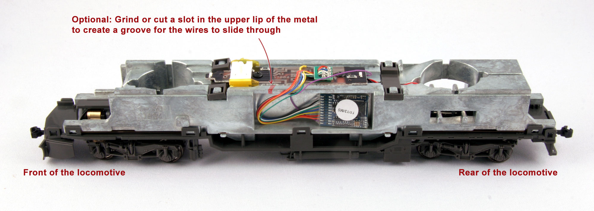 |
Step 10: Install your DCC board and test the unit Plug the 8-pin plug of your decoder of choice into the socket. Make sure that pin 1 (orange) is facing towards the front of the model. Carefully fold the wires down the side of the mechanism and fit the deocder into the cavity in the side of the locomotive. Take care that the wires are not bunched up as they may interfere with the shell's ability to sit securely. Secure the wires and decoder in place and prevent rattling with Kapton or electrical tape. Optional: You may wish to cut a notch in the side of the mechanism with your rotary tool to slot the wires through to prevent them from pressing against the sides of the locomotive shell. This will make it easier to take the shell on and off as well as help protect the wires. |